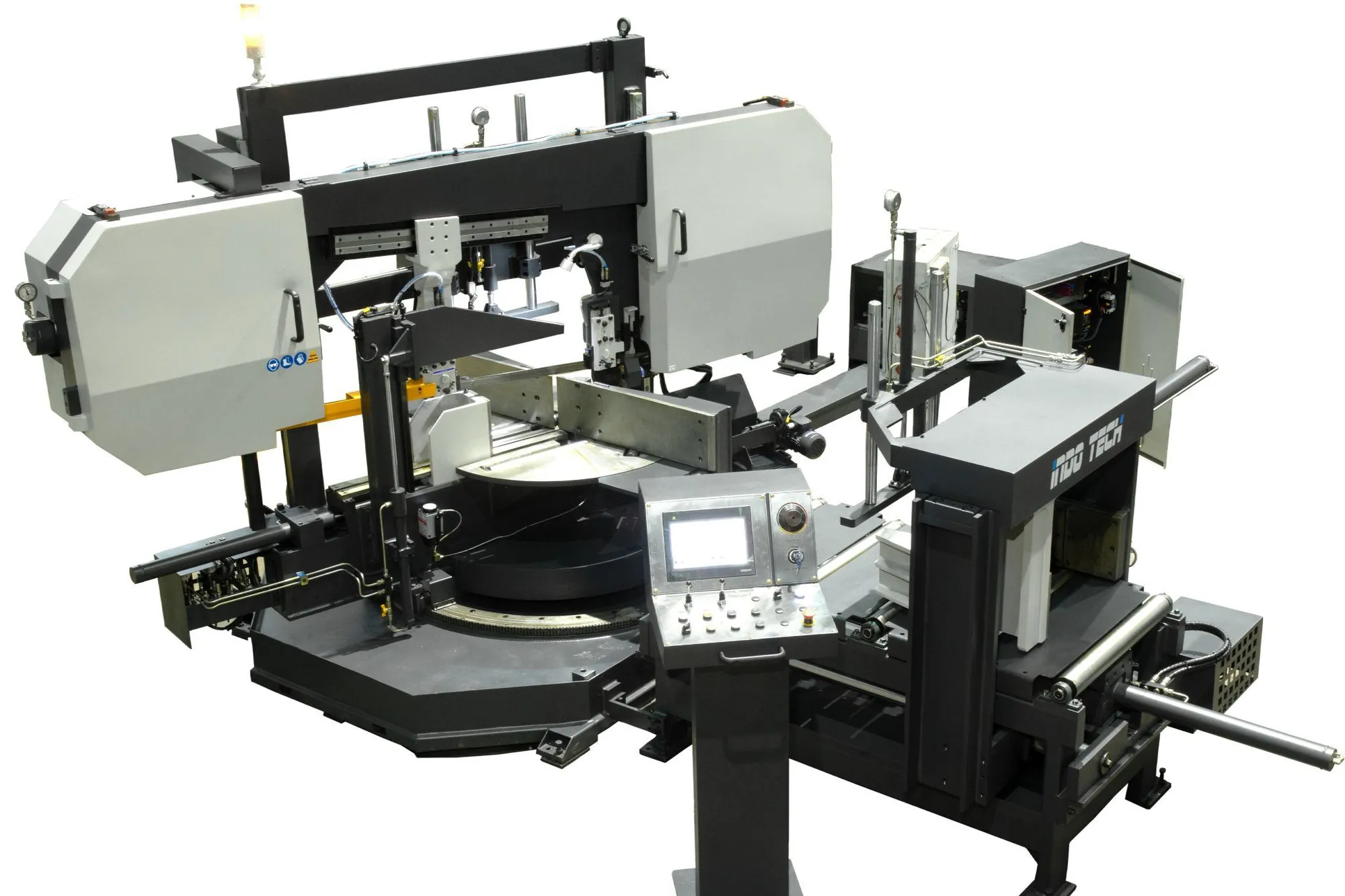


30" x 19" Capacity Dual column, Horizontal Programmable, NC Bandsaw with Omron Control and machine self diagnostics.
| Rect-Cap (H) | 29.53" | 750.06 mm |
| Rect-Cap (W) | 18.9" | 480.06 mm |
| Control | CNC (Omron) | CNC (Omron) |
| Dimensions | 177" x 134" x 96" High | 177" x 134" x 96" High |
| Weight | 8,000 lbs. | 8,000 lbs. |
CUTTING CAPACITY
• 90° (Straight Cut)
Width …………………………………………………….. 29.53"
Height ……………………………………………………. 18.90"
Round ……………………………………………………. 18.90"
• 45° (Left & Right)
Width …………………………………………………….. 18.90"
Height ……………………………………………………. 19.7"
Round ……………………………………………………. 19.7"
• 60° (Left)
Width …………………………………………………….. 13"
Height ……………………………………………………. 18.9"
Round ……………………………………………………. 13"
• Blade Dimensions ……………………………………………….. 296"x 1.5" x .050"
• Main Motor Power ……………………………………………….. 7.5 HP
• Hydraulic Group Motor Power ………………………………….. 2.0 HP
• Cleaning Brush Motor Power …………………………………… 0.16 HP
• Blade Speed ……………………………………………………… 65 – 330 feet/min.
1.2 APPROXIMATE MACHINE DIMENSIONS
Length ………………………………………………………………… 116"
Width ………………………………………………………………….. 95"
Height …………………………………………………………………. 89"
Net Weight ……………………………………………………………. 8,000 lbs.
2.1 COLUMNS AND BOW
Bow is made in electro welded and stabilized steel.
Bow and main column are filled in with concrete polymer.
Bow is supported on two hydraulic cylinders and it is guided in twin prismatic columns.
The Saw Head guiding along the columns is made by high performance lineal guides in the main column, and by support bearings in the secondary column, so that any friction between bow and column is practically avoided, once blade is tensioned.
Blade’s inclined disposition allows aggressive cutting rate to the square surfaces of profiles and bundles, so that the very varying cutting section is equilibrated.
2.2 AUTOMATIC BLADE TENSIONING
Automatic blade tensioning by means of a hydraulic cylinder. This hydraulic cylinder tensions the blade until a prefixed value, keeping always the correct blade tensioning. It has a pressure switch which looks after the correct tensioning and it relaxes the blade when machine is waiting, guaranteeing in this way a lower blade wear. If blade breaks, machine stops automatically.
2.3 BLADE GUIDING
Blade lateral guiding is made with a combination of bearings and hard metal plates allowing
any readjust of blade's position.
Blade's upper guiding is made by bearings, one at each guiding arm, avoiding any cutting
vibration and reducing the noise level during the cut.
The guiding arm is driven by a hydraulic cylinder till the position where the mobile clamp is, so it is not necessary any manual adjustment of the mobile arm to the piece width.
During the cut process, the mobile arm is blocked by hydraulic pistons.
2.4 SAW DRIVING
High performance gearbox specially oversized to support high work loads at low revolutions.
Electronic frequency inverter to control the blade speed change.
Material axle treated and amply sized, assembled over a double line of bearings.
Security blade stop system when blade sticks into the material.
2.5 DOWNFEED AND PRESSURE
Downfeed and pressure are controlled by a varying flow valve, with compensation for different oil and a pressure regulating valve.
By proper regulation of both valves is achieved a precise feed rate.
2.6 FASTENING CLAMPS
The horizontal clamping of material is made on both sides of the blade and the material remains fully bound until the cut ends.
By changing from mitre cut to straight cut or vice versa is not necessary to adjust the position of the clamps, because when the machine rotates, the stationary clamp remains in the direction of the
The fix clamp is grooved and tempered in order to avoid premature wear.
2.7 COOLING: AIR–OIL MIXED SPRAY
Environment friendly lubrication system.
System is composed by several pipes that allow the arrival of the lubrication oil to the directional projection pipes that act in the cutting area.
The oil dropping is intermittent with the possibility of increasing or reducing the dropping frequency depending on need.
Main technical features of the system are:
Exit flow 3-30 mm3/ impulse(variable).
Lubricant deposit: 2 liters
IT IS NECESSARY THAT CUSTOMER HAS A COMPRESSED AIR SYSTEM. AIR MUST BE FILTERED AND DECANTED. THIS SYSTEM WILL NOT BE SUPPLIED BY INDOTECH.
2.8 BLADE CLEANING
Is performed using a rotating brush, driven by an electric motor, allowing rapid readjustment as the brush wears.
2.9 NC MITER POSITIONING (+45º,-60º) (Optional, at extra cost)
The miter positioning system is composed by the following elements:
• A large and accurate ball bearing, calculated to support and turn heavy loads, welded between the support of the machine and its base, allowing the miter positioning of the whole machine.
• Double chain welded in the perimeter of the turning crown.
• NC to control the miter positioning.
There is a display that shows the miter position.
The operator enters in the digital display the required different miter positions and these values remain in memory.
Once the machine is positioned, the turning system is blocked automatically.
2.10 HYDRAULIC INSTALLATION
It is placed in the base of the machine with an easy access, reducing the maintenance time.
2.11 CONTROL AND MANAGMENT
All controls, both hydraulic and electric, are ergonomically placed on a single panel on one side of the cutting installation. The saw also has an additional portable control panel.
The protections of engines and auxiliary circuit are based on Magnetic overloads (no fuses), which allows rapid rearmament fired if any of these protections.
Chip conveyor, powered chip brush, Mist coolant system, Dual vises, 40" Shuttle stroke, Hardened and ground Linear ways, State of art 4 point blade tensioning and Automatic blade tracking, Automatic blade guide adjustment, Helical geared Drive, NC angle positioning, Machine diagnostics. Manuals and 1 year warranty and installation