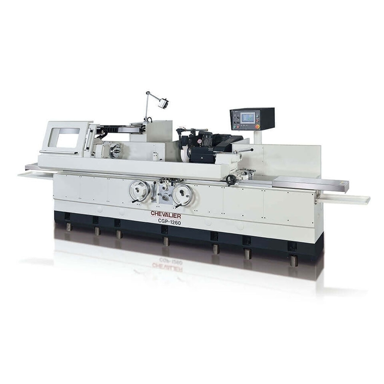
Omicron 1000 E Precision Universal Automatic Cylindrical Grinder
| Swing | 17.913" | 454.99 mm |
| Centers | 39.375" | 1,000.1 mm |
| Power | 7.3 hp | 5.4 kW |
| Workhead Power | 2 hp | 1.5 kW |
| Workhead Speed | 600 RPM | 600 RPM |
| Grinding Wheel Dia. | 17.717" | 450.01 mm |
| Max Weight Between Centers | 40 lb | 18.1 kg |
| Dimensions | R-L 168" X F-B 60" X Height 69" | R-L 168" X F-B 60" X Height 69" |
| Weight | 9,700 Lbs. | 9,700 Lbs. |
Machine Specifications and Feature
TECHNICAL SPECIFICATIONS
OMICRON E 1000
WORKING CAPACITY
Max. distance between centers.....................................39.375"
Max. grinding length..............................................40.551"
Height of centers over table......................................9.05"
Swing over table..................................................17.913"
Max. weight on centers............................................661 Lbs.
Max. weight at 5.9" from spindle nose.............................177 to 220 Lbs.
TABLE
Max. automatic traverse
Hydraulic translation speed mm/min................................0-5000
Manual movement, turn of handwheel................................0.511"
Max. swivel on either side Deg....................................+8° -4°
WORKHEAD
Rotation speed r.p.m.............................................0 - 600
Spindle hole diameter.............................................0.125
Internal center taper.............................................Mt.5
Max. swivel.......................................................Deg.90°
TAILSTOCK
Spindle stroke....................................................1.375"
Spindle diameter..................................................1.88"
Internal center taper.............................................Mt.4
WHEELHEAD
Wheel rotation speed (n.2) r.p.m.................................600-1,600
Max. diameter of wheel...........................................17.717"
Grinding wheel hole diameter.....................................5"
Min. – Max. width of wheel.......................................0.787" - 3.14"
Stroke...........................................................9.84"
Fast hydraulic stroke............................................2.16"
Max. swivel Deg..................................................+/- 180
Handwheel feed stroke............................................7.87"
Additional stroke by sliding on sub-slide base...................5.11"
INTERNAL GRINDING ATTACHMENT (*)
Hole diameter for spindle........................................3.93"
Electric motor...................................................2 hp.
MOTORS
Wheelhead........................................................7.3 hp.
Workhead.........................................................2 hp.
Hydraulic power unit.............................................1 hp.
Coolant pump.....................................................0.241 hp.
DIMENSIONS and WEIGHTS
MAchine Floor Space..............................................R-L 164" x F-B 54"
Height...........................................................69"
Workspace required...............................................R-L 168" xF-B 60"
Net weight.......................................................9,700 Lbs.
STANDARD ACCESSORIES
Coolant equipment complete with pump, tank, pipes,
and nozzle Straight wheel dressing unit mounted on
tailstock (without diamond)
Grinding wheel ø 450 thickness 50 mm bore 127 mm.
Grinding wheel flange
Wheel Head spindle motor inverter driven Micrometric
device for table traverse stop.
Wheel balancing arbor
Wheel extractor
2 hard metal tipped centers.
Set of levelling screws and plates
2 steel sheets for table guide protection
Sliding doors
Set of service spanners
Set of hexagonal spanners
5 Kg. oil for wheel spindle lubrication
5 Kg. oil for guide lubricating
Instructions manual
220 volts 60 hz 3 phase
Inch system
EQUIPMENT
Two axis DRO display. SPACE 2.000
Incremental linear encoder for micro positioning of wheelhead.
Incremental linear encoder for micro positioning of table
Electric installation 24V
Hydraulic unit complete (without oil)
Pneumatic unit
Centralized lubrication
Table manual swiveling system for taper grinding with dial gauge
Included Optional Accessories
Grinding wheel flange, complete with external counterweight bore diam. 127 mm.
Tailstock manual with micro adjustment for the correction of cylindricity +/- 0.1 mm
Self-centering chuck double guide complete with 3 hard jaws for externals,
3 hard jaws for internals, 3 soft jaws and safety locking key external diameter
180 mm.
Blank adapter flange diameter 180 mm Spindle attachment MK 5.
Combined magnetic and paper filtration unit complete with installation, electric
equipment, and coolant tank. Filtration capacity 80 l/min Coolant tank capacity
approx. 250 l.
Mist collector and filter for emulsifying oil fog complete with installation
Maximum air flow 600 m³/h
Radius dressing devices, cap. 0-10 mm suitable for height of centers up to 250 mm.
Diamond holder mounted on the table for wheel side surface. Suitable for height
of centers up to 250 mm
Work lamp n.1 LED 24V type up to machine size 1000 mm between centers.
Interface for remote assistance this function allows remote operation and remote
monitoring of the user interface of the control system. The remote access is
established via a secure connection based on TLS (previously SSL) via the Internet.
The technical implementation of access to the Internet is through LAN connection.
PERFORMANCE AND PRECISION DEGREE
Robbi grinding machines are according to the international precision norms ISO 2433.
The table movement linearity is guaranteed by a max. Deviation of 0,002 mm./m.
Surface finish degree 0, 2 Ra (**)
The obtainable grinding roundness is:
- grinding between centers 0.3 (**)
- grinding with Live centers 0.4 (**)
(**) for a test workpiece ground in our factory during machine testing
The Grinding Machine is composed of:
BASE
Structure in normalised and stabilised cast iron with large ground guides. The lubrication plant provides oil to the guides by means of a constant oil flow distributed on the complete length. In the middle of the base there is located the hydraulic cylinder for the longitudinal table movement. On the lower part of the perimeter are situated the recesses for machine levelling. Considering the base structure, usually a foundation is not required.
TABLE
The table is manufactured in two parts, both are in normalised and stabilised cast iron. The lower part has large ground guides, accurately hand scrapped to permit a better sliding. The upper part is swivel able in the two directions suitable for grinding tapered workpieces. This part includes a micrometric device with centesimal dial gauge for taper control.
WORKHEAD
The structure in normalised, stabilised, and well ribbed cast iron, allows to support the workpiece weight and the force generated by the grinding operation. It is equipped with fixed and turntable spindle. The spindle rotates on high precision ball bearings, guaranteeing restricted tolerance and maximum rigidity in the working. The spindle rotation is assured by a double polarity three phase motor (two rotation speeds). The r.p.m. change is obtained with a belt-change.
WHEELHEAD
The structure is composed of two carriages in normalised cast iron. The upper carriage where the hydrodynamic spindle is located, has a manual stroke positioning of 130 mm. and the air flow facilitates the movement. The lower carriage which slides on hand scrapped guides, has two movements:
• fast approach by means of a hydraulic cylinder.
• working feed by means of a steel screw and bronze preloaded nut.
On request it is possible to assemble an optic rule for micro positioning (0,001 mm.)
The wheelhead rotates +/- 45°.
WHEELHEAD SPINDLE
Hydrodynamic type rotates on anti-friction metal bushes, which guarantees a high finish degree. The rotation is by means of an AC motor. On request, the speed may be regulated by an inverter. The transmission is by means of a pulley and Poly-V belt. On request, the machine may be supplied with a second grinding wheel on the right-hand side.
TAILSTOCK
Together with the workhead the tailstock supports the workpiece weight and the force generated by the grinding operation. The structure is in normalised and stabilised cast iron. On request, it may be supplied with a hydraulic treadle drive and safety device against accidental opening. The spindle opening is possible only with the grinding wheel in back position.
MANUAL GRINDING WHEEL FEED HANDWHEELS
1 - The main handwheel has a division of 0.01 mm. on the diameter. With one complete turn of the
Handwheel, the wheelhead will feed 2 mm. on the diameter.
2 - The micrometric handwheel has a division of 0.002 on the diameter. With one complete turn of the
Handwheel, the wheelhead will feed 0.05 mm. on the diameter.
MANUAL TABLE FEED HANDWHEEL
Is automatically disengaged when the hydraulic table movement is engaged.
DIAMOND DRESSER
The external diamond dressing device is very strong and is position on the tailstock.
The internal diamond dressing device is positioned on the table.
EQUIPMENT AND ELECTRICAL PLANT
In a cabinet, separate from the machine.
HYDRAULIC PLANT
The hydraulic power pack is separate from the machine and activates the hydraulic cylinders of the table and fast wheelhead approach. It also activates the hydraulic cylinder of the tailstock when this system is requested. It is equipped with an oil-air heat exchanger. Supplied without hydraulic oil.
LUBRICATION PLANT
The lubrication power pack is separate from the machine and supplies continuous oil to the wheelhead and table guides. The recovered oil is filtered and then resent to the power pack.
PNEUMATIC PLANT
Has the function to make lighter the wheelhead over-slide, during the manual movements.
COOLANT PLANT
Large capacity tank for the coolant water. On request, it is possible to equip the coolant plant with a magnetic or paper roll or combined magnetic paper roll cleaner. The coolant flow is automatic; each time that the grinding wheel approaches the workpiece it starts and each time that the grinding wheel retracts from the workpiece it stops.
PROTECTIONS
For the protection of the operator all movable parts are covered with suitable guards. Precisely: carter for belts, carter for grinding wheel and sheets for guides. The front protection is a sheet sliding door with poly-carbonate shield. A movable shield in sheet, controlled by a pneumatic cylinder, protects the operator, when the grinding wheel is in rotation and the front sliding door is open. A safety device does not permit the automatic cycle to start if the front sliding door is open.
Valid Period
This quotation is valid for a period of 30 days. The prices and delivery are based on costs and conditions existing on the date of quotation and may be subject to change by Ecotech before final acceptance of your order. Ecotech reserves the right to amend any accidental errors and/or omissions on quotations at the time of acceptance of an Order.